Arduino has been around for years, and you've probably heard the term. It is an open-source electronics platform that allows developers to connect hardware with software easily. The popularity of Arduino is vast because it offers a simple and accessible user experience. As an iOS developer, I wanted to play around with this platform, so I've built a toy car that can be controlled with a mobile app. Read this article to find out how I did it.
Project outline
There are two key components in this project:
Arduino based toy car.
iOS application for controlling it (connected via Bluetooth Low Energy)
You can see the final result in the picture below. On the left side is an iOS application, on the right side, a toy car.

iOS application
Let’s start with the car controller (iOS application). In this article, I won't go into details about iOS application implementation. I will describe briefly how it works from the user perspective.
The application connects to Arduino using BLE (Bluetooth Low Energy).
After launching it, the device discovery screen is displayed. The application starts searching for Bluetooth devices automatically and displays devices with matching service UUID. User can restart device discovery by pressing the Search button (in case of network errors). The application can automatically connect to the last selected device by checking the Auto-connect checkbox.
The controller screen has four controls:
Drive forward and backward (bottom left corner)
Turn left and right (bottom right corner)
Change gear (buttons 1-5)
Headlights on/off (top right corner)
It shows connection status in the top right corner. By pressing the back button, the application disconnects from the car and navigates back to the device discovery screen.
Toy car
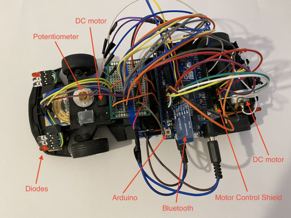
The toy car was built using mechanical parts from an old toy: chassis with wheels and 2 DC motors (one for driving, the other one for turning).
The custom components are Arduino, DC motor controller, Bluetooth, LEDs.
How to build it?
Hardware components
1. Arduino Due
Arduino is an open-source electronics platform based on easy-to-use hardware and software. It can be used for prototyping hardware devices. Implementation is very fast and in a few days, we can have a working device for real-world testing.
It is responsible for controlling hardware components (motors, sensors, LEDs), Bluetooth communication, and handling iOS application commands.
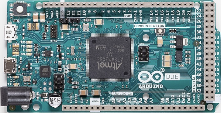
Arduino Due main characteristics:
32-bit ARM core microcontroller (84 MHz clock)
54 digital input/output pins (of which 12 can be used as PWM outputs)
12 analog inputs
4 UARTs (hardware serial ports)
Board runs at 3.3V (unlike most Arduino boards that run at 5V)
Compatible with all Arduino shields that work at 3.3V
2. Waveshare Motor Control Shield L293D
It is capable of driving 4 DC motors or 2 stepper motors at one time.
When using an external power supply of 9V it allows you to adjust the speed and direction of the motors with current consumption up to 600mA (1.2A peak) and a voltage between 1.25V - 6.45V.
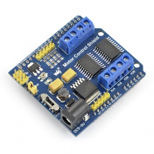
Toy car has two DC motors: the first one is used for driving, the second one for turning.
3. Bluetooth module HM-10
HM-10 is a Bluetooth 4.0 module. It works with voltage from 3.3V to 5V, it communicates over a serial UART interface (RX, TX pins). The maximum transmitter power is +6 dBm, the receiver sensitivity is -23 dBm.
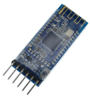
4. Two DC motors
DC motor for driving (operation Voltage of 3-6V, free-run current of 200mA).
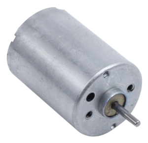
Mini DC motor for turning (operation Voltage of 3-6V, free-run current of 30mA).
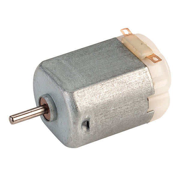
Choose your DC motors depending on the weight of the car.
5. LED lights
4 x red LEDs for turn signals
4 x white LEDs for headlights

6. Other components
8 resistors 220Ω
Potentiometer 10kΩ
6 AA batteries (1.5V)
Wires
Breadboard
Old toy car chassis
How to connect everything?
The photo below shows how components are connected. It doesn’t look pretty, but I assure you that it works 🙂
And here is a schematic diagram:
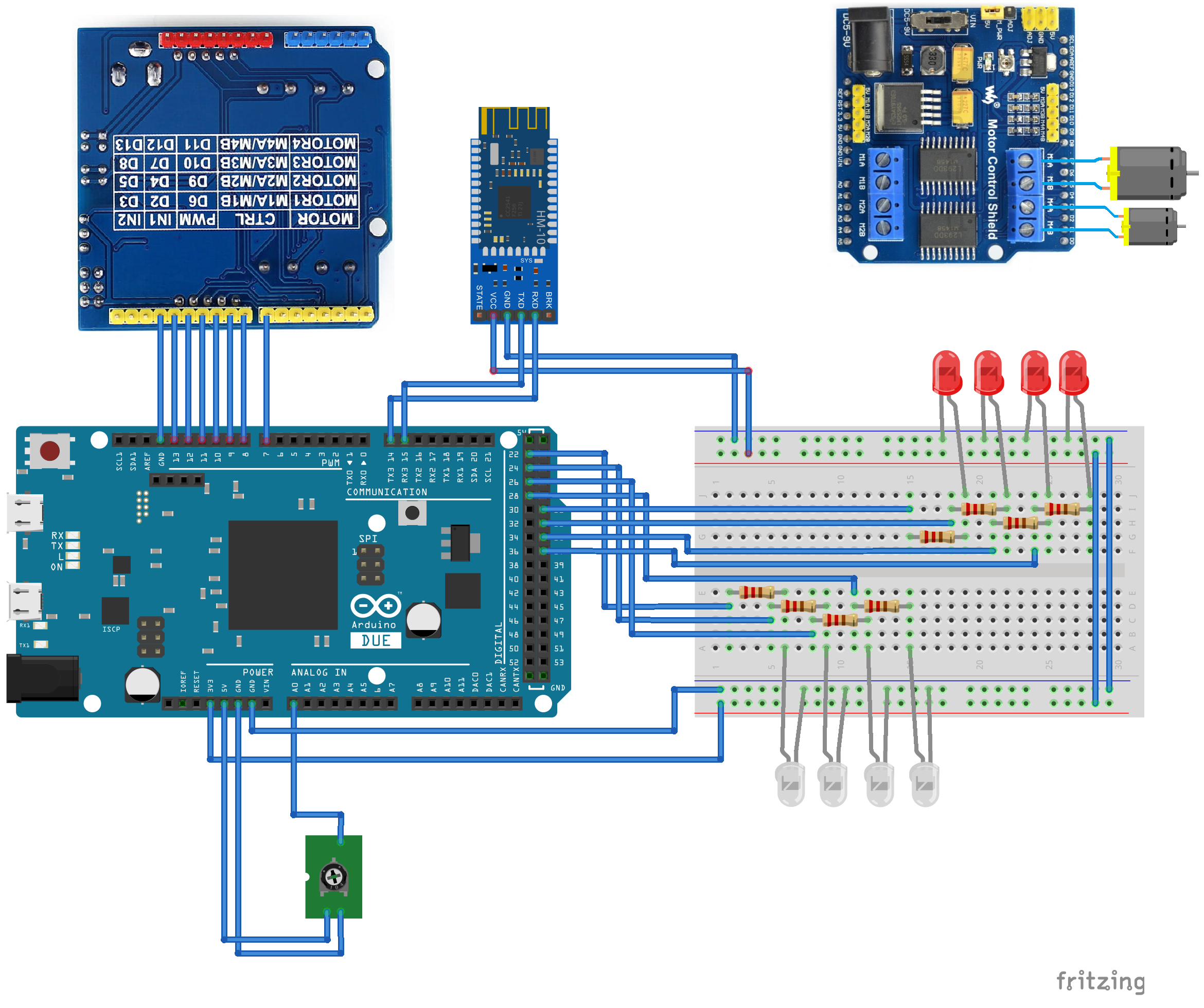
Let’s examine each and every component individually.
1. Bluetooth and the main application loop
One of the biggest advantages of Arduino is that there is a vast set of ready to use components and libraries available. They are very easy to use and don’t require us to write much code. They are named Shields. In this project, I used a Bluetooth Module and a DC Motor Control Shield.
Let’s start with the Bluetooth module first. It communicates with the Arduino board using the Serial port.
Connect Bluetooth module HM-10 pins to Arduino board:
VCC > VCC (5V or 3.3V)
GND > GND
RX > TX3
TX > RX3
Main application setup
Define a helper macro named HC06 that points to a Serial3. configureBle() method starts Bluetooth connection.
1
2
3
4
5
6
#define HC06 Serial3

void configureBle() {
  HC06.setTimeout(100);
  HC06.begin(9600);
}
Define Bluetooth commands for controlling the toy car. iOS application sends commands to the Arduino. Currently, the application supports the following commands: drive, turn on headlights, change gear, turn.
Command length is 3 bytes.
First byte is a command code defined as an enum BleApiCommand.
Second byte is an additional parameter, depending on the command code:
cmdDrive - speed: 0-127 (drive backwards), 127 (stop), 128-255 (drive forward).
cmdHeadlights - 1 (turn headlights on), 0 (turn headlights off).
cmdGear - gear integer between 1-5.
cmdTurn - turn angle: 0-126 (left), 127 (straight), 128-255 (right).
Third byte is a command terminator 0x0f.
1
2
3
4
5
6
7
8
9
const int commandTerminator = 0x0f;
const int commandLength = 3;

enum BleApiCommand {
    cmdDrive = 0x23,
    cmdHeadlights = 0x24,
    cmdGear = 0x25,
    cmdTurn = 0x40
};
Main application setup method.
1
2
3
4
5
void setup() {
    configureLightsPins();
    configureMotorPins();
    configureBle();
}
Main application loop
Main application loop responsibilities:
Read the Bluetooth command. If it is valid, invoke a handleCommand() method. It supports the following commands: drive, turn headlights on and off, change gear, turn.
Turn signals work automatically when car turns, it is handled inside a turnSignalControllerTick() method.
handleTurn() method positions front wheels to the given angle.
stopIfDisconnected() stop car if controller is disconnected.
1
2
3
4
5
6
7
8
9
10
11
12
13
14
15
16
void loop() {
    int tickTime = millis();
    // Command loop
    while(HC06.available()) {
        byte buffer[commandLength];
        int size = HC06.readBytes(buffer, commandLength);
        if (size != commandLength) {
            continue;
        }
        lastCommandTimestamp = tickTime;
        handleCommand(buffer);
    }
    handleTurn();
    turnSignalControllerTick(tickTime);
    stopIfDisconnected(tickTime);
}
Handling commands
Extract command code and parameter, then handle each command in a separate method.
1
2
3
4
5
6
7
8
9
10
11
12
13
14
15
16
17
18
19
20
21
22
23
24
25
26
27
void handleCommand(byte data[]) {
    byte code = data[0];
    byte param = data[1];
    byte terminator = data[2];
    if (terminator != commandTerminator) {
        return;
    }
    switch (code) {
        case cmdHeadlights: {
            bool on = param == 0x02;
            setHeadlights(on);
            break;
        }
        case cmdGear: {
            setGear(param);
            break;
        }
        case cmdTurn: {
            turnWheels(param);
            break;
        }
        case cmdDrive: {
            drive(param);
            break;
        }
    }
}2. Headlights and turn signals
Headlights
Headlights (white LEDs) can be turned on and off manually by the user using a button in the top-right corner of an iOS application.
Connect each LED to a separate digital PIN through a resistor (220Ω) as shown in the diagram above.
Declare 4 headlights and 4 turn signals pins as constants and set their mode to OUTPUT.
1
2
3
4
5
6
7
8
9
10
11
12
13
14
15
const int pinHeadlightsRight1 = 22; // Remaining headlights pin numbers: 24, 26, 28
const int pinTurnSignalLeftFront = 31; // Remaining turn signals pin numbers: 33, 35, 37
void configureLightsPins() {
    pinMode(pinHeadlightsRight1, OUTPUT);
    pinMode(pinTurnSignalLeftFront, OUTPUT);
    ...
}

void setHeadlights(bool on) {
  int value = on ? HIGH : LOW;
  digitalWrite(pinHeadlightsRight1, value);
  digitalWrite(pinHeadlightsRight2, value);
  digitalWrite(pinHeadlightsLeft1, value);
  digitalWrite(pinHeadlightsLeft2, value);
}
Turn signals
Turn signals (red LEDs) work automatically - they blink every 0.5 seconds when the car is turning. They work in four modes: disabled, blink left, blink right, blink both sides.
Define mode as an enum and tick interval as constant.
Use turnSignalControllerSetMode() method to change the blinking mode.
1
2
3
4
5
6
7
8
9
10
11
12
13
14
15
16
17
18
19
20
enum Modes {
    idle = 0,
    blinkLeft = 1,
    blinkRight = 2,
    blinkBoth = 3
};

const int tickInterval = 500; // milliseconds
int lastTickTimestamp = 0;
int mode = idle;
bool ledOn = false;

void turnSignalControllerSetMode(int newMode) {
    if (newMode == mode) {
      return;
    }
    mode = (Modes)newMode;
    lastTickTimestamp = 0;
    updateState();
}
turnSignalControllerTick() method is called from the main application loop. lastTickTimestamp stores the last timestamp (number of milliseconds passed since the Arduino board began running the current program) and compares it with the current timestamp. The result is a timer with a 500ms interval.
1
2
3
4
5
6
7
void turnSignalControllerTick(int currentTimestamp) {
    if (mode == idle) { return; }
    if ((currentTimestamp - lastTickTimestamp) > tickInterval) {
      lastTickTimestamp = currentTimestamp;
      updateState();
    }
}
Method updateState() turns LEDs on and off depending on the current mode.
1
2
3
4
5
6
7
8
9
10
11
12
13
14
15
16
17
18
19
20
21
22
23
24
25
26
27
28
void updateState() {
  if (mode == idle) {
    ledOn = false;
  } else {
    ledOn = !ledOn;
  }
  int value = ledOn ? HIGH : LOW;
  switch (mode) {
  case idle:
  case blinkBoth:
    digitalWrite(pinTurnSignalLeftFront, value);
    digitalWrite(pinTurnSignalLeftRear, value);
    digitalWrite(pinTurnSignalRightFront, value);
    digitalWrite(pinTurnSignalRightRear, value);
    break;
  case blinkLeft:
    digitalWrite(pinTurnSignalLeftFront, value);
    digitalWrite(pinTurnSignalLeftRear, value);
    digitalWrite(pinTurnSignalRightFront, LOW);
    digitalWrite(pinTurnSignalRightRear, LOW);
    break;
  case blinkRight:
    digitalWrite(pinTurnSignalLeftFront, LOW);
    digitalWrite(pinTurnSignalLeftRear, LOW);
    digitalWrite(pinTurnSignalRightFront, value);
    digitalWrite(pinTurnSignalRightRear, value);
    break;
}3. Driving
Connect DC motors to the Motor Control Shield L293D:
DC motor for driving to M3 interface.
DC motor for turning to M4 interface.
Define and configure DC the motor pins
1
2
3
4
5
6
7
8
9
10
11
12
13
14
15
16
17
18
19
20
21
22
23
const int pinMotorDrive_dir1 = 8;
const int pinMotorDrive_dir2 = 7;
const int pinMotorDriveSpeed_pwm = 10;
const int pinMotorTurn_dir1 = 12;
const int pinMotorTurn_dir2 = 13;
const int pinMotorTurnSpeed_pwm = 11;

void configureMotorPins() {
    pinMode(pinMotorDrive_dir1, OUTPUT);
    pinMode(pinMotorDrive_dir2, OUTPUT);
    pinMode(pinMotorDriveSpeed_pwm, OUTPUT);
    pinMode(pinMotorTurn_dir1, OUTPUT);
    pinMode(pinMotorTurn_dir2, OUTPUT);
    pinMode(pinMotorTurnSpeed_pwm, OUTPUT);
    digitalWrite(pinMotorDrive_dir1, 1); // set forward direction
    digitalWrite(pinMotorDrive_dir2, 0); // set forward direction
    digitalWrite(pinMotorDriveSpeed_pwm, HIGH); // set to high to enable the L293 driver chip
    analogWrite(pinMotorDriveSpeed_pwm, 0); // set speed to 0
    digitalWrite(pinMotorTurn_dir1, 1); // set forward direction
    digitalWrite(pinMotorTurn_dir2, 0); // set forward direction
    digitalWrite(pinMotorTurnSpeed_pwm, HIGH);  // set to high to enable the L293 driver chip
    analogWrite(pinMotorTurnSpeed_pwm, 0);  // set speed to 0
}
Handle the drive command
Speed parameter (0-127 - drive backwards, 127 - stop, 128-255 - drive forward) must be converted into a speed (0-255) and direction. Choose the minimum speed/voltage depending on the car weight and DC motor parameters.
1
2
3
4
5
6
7
8
9
10
11
12
13
14
15
16
17
18
19
void drive(byte value) {
    int minSpeedValue = 100;
    int maxSpeedValue = 255;
    if (value < 127) { // backwards
        digitalWrite(pinMotorDrive_dir1, 0);
        digitalWrite(pinMotorDrive_dir2, 1);
        int speedValue = minSpeedValue + (maxSpeedValue - minSpeedValue) * (127 - value) / 127;
        analogWrite(pinMotorDriveSpeed_pwm, speedValue);
    } else if (value > 127) { // forward
          digitalWrite(pinMotorDrive_dir1, 1);
          digitalWrite(pinMotorDrive_dir2, 0);
          int speedValue = minSpeedValue + (maxSpeedValue - minSpeedValue) * (value - 127) / 127;
         analogWrite(pinMotorDriveSpeed_pwm, speedValue);
    } else { // 127 stop
          digitalWrite(pinMotorDrive_dir1, 1);
          digitalWrite(pinMotorDrive_dir2, 0);
          analogWrite(pinMotorDriveSpeed_pwm, 0);
    }
}4. Turning
Read current front wheels angle using a potentiometer
Connect potentiometer pins to the board:
First outer pin to the ground
Second outer pin to 5V
Middle pin to the Arduino analog pin number A0
1
2
3
4
5
6
const int pinPotentiometer = A0;

int readPotentiometer() {
    int sensorValue = analogRead(pinPotentiometer);
    return sensorValue;
}
Convert the target angle
Convert target angle received from an iPhone (0-255) to integer (0-1024) in order to compare it with the potentiometer reading.
1
2
3
4
5
6
7
8
9
10
11
12
13
14
15
16
17
18
19
void turnWheels(byte value) {
    int minLeft = 300; // it means that the wheels are turned all the way to the left
    int maxRight = 900; // wheels turned all the way to the right
    int center = 600; // wheels are straight
    if (value < 127) { // turn left
        turnSignalControllerSetMode(1);
        float factor = ((float)value)/127.0;
        targetTurnValue = minLeft + factor * (center - minLeft);
    } else if (value == 127) { // straight
          turnSignalControllerSetMode(0);
          targetTurnValue = center;
      } else if (value > 127) { // turn right
          turnSignalControllerSetMode(2);
          float factor = ((float)value - 127.0) / 128.0;
          targetTurnValue = center + 1 + factor * (maxRight - center - 1);

      }

}
Turn wheels
Method handleTurn() does a few things:
Reads the current wheels angle using the potentiometer. analogRead()returns integer value between 0-1024 which represents an angle.
Calculates which direction to turn the wheels to - left, right, or stop when the angle is reached.
Starts/stops turn signals.
Choose the speed/voltage depending on the DC motor parameters.
1
2
3
4
5
6
7
8
9
10
11
12
13
14
15
16
17
18
19
void handleTurn() {
    int sensorValue = readPotentiometer();
    const int tolerance = 20;
    const int speed = 130;
    if (abs(sensorValue - targetTurnValue) < tolerance) {
        // value reached, stop motor
        analogWrite(pinMotorTurnSpeed_pwm, 0);
    } else if (sensorValue > targetTurnValue) {
        // turn left
        digitalWrite(pinMotorTurn_dir1, 0);
        digitalWrite(pinMotorTurn_dir2, 1);
        analogWrite(pinMotorTurnSpeed_pwm, speed);
    } else if (sensorValue < targetTurnValue) {
        // turn right
        digitalWrite(pinMotorTurn_dir1, 1);
        digitalWrite(pinMotorTurn_dir2, 0);
        analogWrite(pinMotorTurnSpeed_pwm, speed);
    }
}
That’s pretty much everything. I hope you enjoyed this article and you will build your toy car!

Krzysztof Pelczar
iOS Developer
